ALINX AX7020 Bring-up: Mainline U-Boot Over JTAG, No FSBL, No Serial Cable
Stephan BökelmannI thought this would be an afternoon. Load a bootloader over JTAG, poke it a bit, write it into flash: how hard can it be? It took the better part of a day and nine distinct detours, from cache lines silently corrupting a loaded image to a QSPI controller that reads everything three bytes off, but only in SPL, and only in quad mode.
This post is Stage 1 of the bitstream pipeline plan: an ALINX AX7020 (Zynq-7000, XC7Z020) that powers on and boots mainline U-Boot out of QSPI flash by itself: no Xilinx FSBL, no vendor U-Boot fork, no JTAG adapter attached, and no serial cable ever connected. The console is U-Boot’s netconsole over UDP; the whole board is operated from the workstation over Ethernet.
The structure follows how I wish someone had written it for me: first the walkthrough that actually works, reproducible on a clean machine and a clean board. Then, at the end, every detour, because the detours are where the learning was, and because most of them will bite anyone doing this on any Zynq board.
U-Boot 2026.10-rc2 (Aug 30 2026 - 20:25:52 +0200)
modeboot      = qspiboot
DRAM size     = 0x40000000        (1 GiB)
DDR frequency = 533 MHz
ARM frequency = 766 MHz
SF: Detected w25q256 with page size 256 Bytes, erase size 64 KiB, total 32 MiB
IP addr       = 192.168.77.77     (DHCP)
That is the end state. Here is the way there.
The seven checkpoints
Every stage of this bring-up ends in something you can test. That is important, because most failures on this road are silent, and without a defined “this must now be true” you cannot tell which layer broke. The walkthrough is built around seven such checkpoints:
| # | After | What must be true |
|---|---|---|
| 1 | OpenOCD scan | two TAPs found: Xilinx PL (0x23727093) and ARM DAP, both cores attached |
| 2 | telnet into OpenOCD | halt stops the CPU at the BootROM park point; mdw reads SLCR |
| 3 | U-Boot build | mkimage -l validates both images; fdtget finds the model and the flash@0 node in the SPL DTB |
| 4 | lab network setup | host address, route, DHCP server and TFTP server verifiably up, board not needed |
| 5 | JTAG bring-up | board takes a DHCP lease, netconsole is interactive, bdinfo/sf probe/mii info answer correctly |
| 6 | flashing | read-back MD5 of both flash regions equals the host’s md5sum |
| 7 | standalone boot | after a power cycle with J13 on QSPI: lease within ~5 s, banner shows modeboot = qspiboot, console interactive |
If a checkpoint fails, everything before it is known-good. That is the whole point. Every self-written file that appears below (OpenOCD configs, device tree, defconfig, host tools) is available at github.com/MaxClerkwell/ax7020-bringup. Now the walkthrough.
The hardware
| Board | ALINX AX7020, XC7Z020-2CLG400, JTAG IDCODE 0x23727093 |
| DDR3 | 2× MT41J256M16, 32-bit bus, 533 MHz → 1 GiB |
| QSPI | Winbond W25Q256, 32 MiB, single chip select, MIO 1..6 |
| UART | PS UART1 on MIO 48/49 via CP2102 (not used, no serial console) |
| Ethernet | PS GEM0, RGMII on MIO 16..27, MDIO on MIO 52/53, RTL8211E-VL at PHY address 1 |
| SD | MIO 40..45, card detect MIO 47 |
| USB | ULPI on MIO 28..39, reset MIO 46 (active low) |
| Boot jumper | J13: left pins = SD, middle = QSPI, right = JTAG |
The on-board JTAG adapter is a bare FTDI FT232H (0403:6014) wired to the
four MPSSE pins only. First curiosity of the day: it enumerates on USB
regardless of whether the board’s power switch is on: the FT232H hangs on
USB VBUS, not on the board supply. That is a design choice, and the cheaper
of two common ones. Standalone FTDI dongles and low-cost dev boards power
the adapter from the host; Digilent and the Xilinx eval boards instead feed
their on-board FTDI from the board supply (or put it behind a level shifter
referenced to the target voltage), so the adapter only appears once the
board is up. Professional external adapters go further still and sense
VTREF before driving anything. The bus-powered variant has a wrinkle beyond
the confusing enumeration: it drives TCK/TDI/TMS into an unpowered Zynq,
whose ESD protection diodes clamp those levels onto the dead supply rail,
weakly back-powering the switched-off board. At an FTDI pin’s few mA this
is usually harmless, but tidy design it is not. The practical lesson holds
for any bus-powered adapter, which is most of the cheap ones: lsusb
showing the adapter proves the cable, nothing more; whether a live JTAG
chain sits behind it is a separate question that a scan answers, not
enumeration.
Host tools: arm-none-eabi-gcc 15.2, OpenOCD 0.12.0, Python 3.13. No Vivado,
no Vitis, no Xilinx tool of any kind.
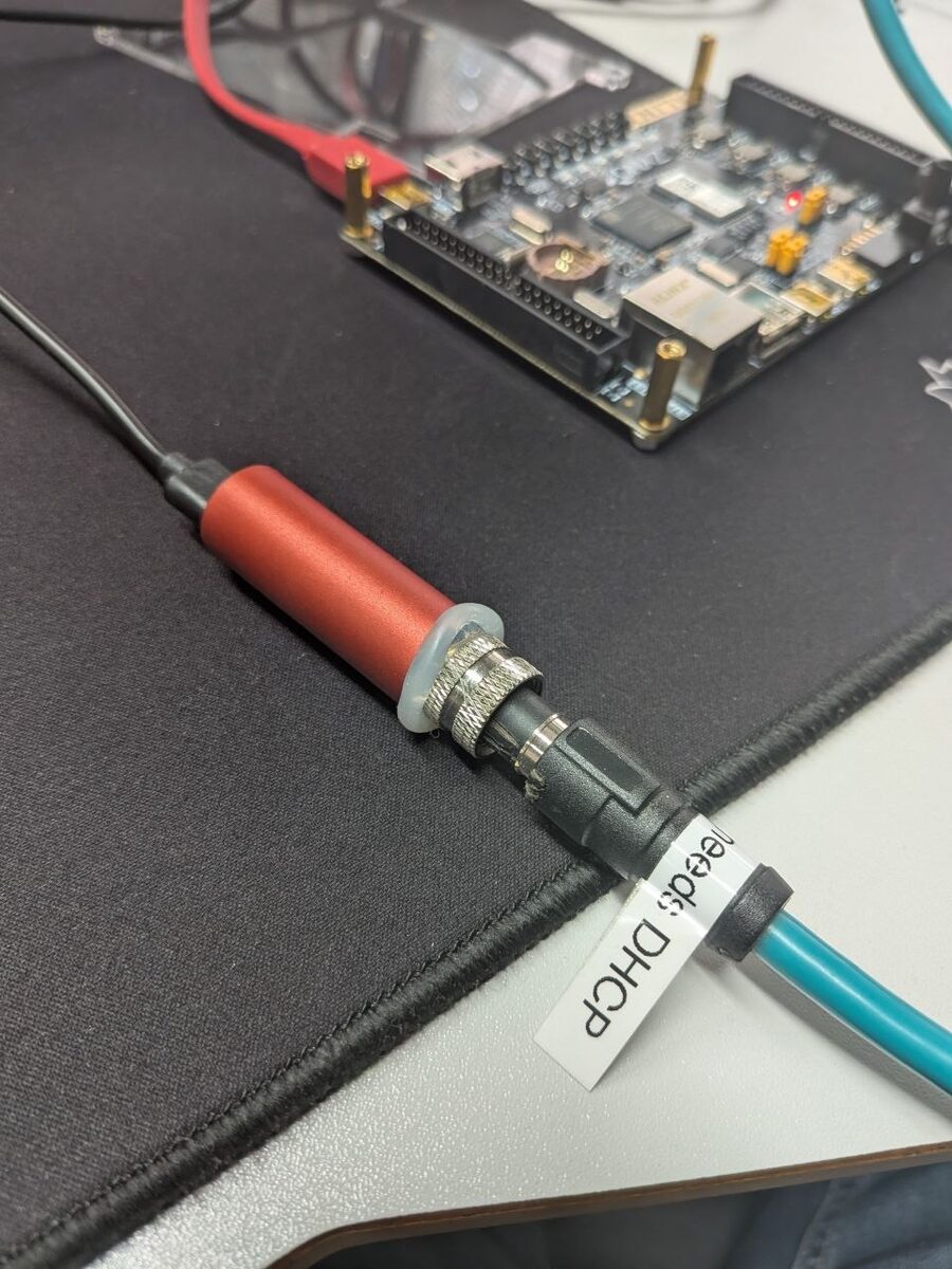
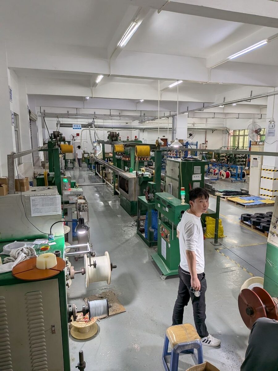
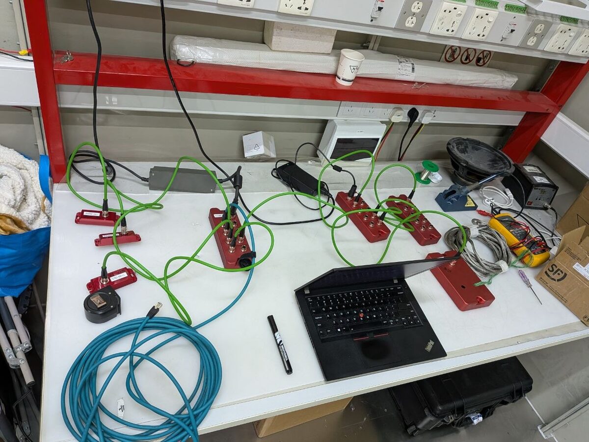
Side note on the physical link: the Ethernet connection runs through the M12 adapter from Auto-Intern GmbH, which I co-developed; the cable comes from Dongguan Guanghui Electronic Technology (GH Electronic). In March I visited their factory and worked out our Ethernet cable specifications with their engineers; the same cables now ship with Auto-Intern’s new skAInet Edge-Compute. Industrial Ethernet cabling (M12 X-coded, shielding, IP rating, EMC and the certification paperwork that goes with it) is a topic I enjoy, and I am happy to help teams in the EU and the USA specify and certify correct cables. Get in touch if that is a problem you have.

Step 1: Talk to the chip with OpenOCD
OpenOCD is a translator. On one side it talks to a USB adapter, on the other
side to a debug port on a chip, and it knows nothing about either until you
tell it. That is why you always hand it two files: one describing the
adapter, one describing the target. The target file is usually someone
else’s problem: target/zynq_7000.cfg ships with OpenOCD and describes the
whole chain: a Xilinx TAP for the programmable logic, an ARM DAP for the
processing system, two Cortex-A9 cores. The adapter file is yours; nobody
upstream knows what the vendor wired up. Running only the target file fails
with Error: Debug adapter does not support any transports?.
Three questions for an unknown board, in order:
- Which chip drives the USB side?
lsusb.0403:6014= FT232H → OpenOCD’sftdidriver (MPSSE).1366:xxxxwould be J-Link,0d28:0204CMSIS-DAP: a different driver, not a different pin table. - Which pins carry TCK/TDI/TDO/TMS? On FTDI fixed in silicon: ADBUS0–3. Anything beyond (reset, buffer enable) has to come from the schematic (for the AX7020 I could reconstruct this from the ALINX datasheets/schematic) or from the test: configure only the four mandatory pins and see whether the chain answers. It did, so nothing else is required here.
- Anything between FTDI and chip? A buffer or mux shows up as all-ones or all-zeros in the scan. Not on this board.
That yields openocd/ft232h.cfg, complete:
adapter driver ftdi
ftdi vid_pid 0x0403 0x6014
ftdi layout_init 0x0008 0x000b    # TMS idles high; TCK/TDI/TMS out, TDO in
adapter speed 1000
transport select jtag
layout_init is the working line: low byte = idle levels (0x0008: TMS
high, keeping the TAP in reset until OpenOCD takes over), high byte =
directions (0x000b: bits 0, 1, 3 out; TDO in). Every untouched pin stays
an input.
openocd -f openocd/ft232h.cfg -f target/zynq_7000.cfg
Success, with the board powered and J13 on JTAG, is checkpoint 1:
Info : JTAG tap: zynq_pl.bs tap/device found: 0x23727093 (mfg: 0x049 (Xilinx), part: 0x3727, ver: 0x2)
Info : JTAG tap: zynq.cpu tap/device found: 0x4ba00477 (mfg: 0x23b (ARM Ltd), part: 0xba00, ver: 0x4)
Info : zynq.cpu0: hardware has 6 breakpoints, 4 watchpoints
Info : zynq.cpu1: hardware has 6 breakpoints, 4 watchpoints
Info : Listening on port 4444 for telnet connections
Part 0x3727 is an XC7Z020, the DAP is reachable, both A9s attached. Note
that OpenOCD is now a server, not a prompt: the FT232H is the interface,
JTAG the protocol, OpenOCD the daemon that owns the adapter and translates
whatever a client asks (telnet on 4444, gdb on 3333, Tcl on 6666) into
JTAG transactions. From the client side you never see TAPs or scan chains,
only a chip with registers and memory.
Do this telnet test once in any case; it is checkpoint 2 of the bring-up (checkpoint 1 being the two TAPs in the scan). Since OpenOCD occupies its terminal as a server, you need a second terminal for it:
$ telnet localhost 4444
> halt
target halted in ARM state due to debug-request, current mode: Supervisor
cpsr: 0x000001d3 pc: 0xffffff34
MMU: disabled, D-Cache: disabled, I-Cache: disabled
> mdw 0xF8000000
0xf8000000: 00000000
PC 0xffffff34 is inside the BootROM, where a Zynq with the jumper on JTAG
parks, waiting for exactly this. mdw on the SLCR block proves memory-mapped
access through the DAP.
One caveat before moving on: JTAG sees the chip, not the board. IDCODE,
device DNA, SLCR state (including the boot-mode pins at 0xF800025C): all
readable. DDR population, MIO wiring, flash type: not. The DDR controller
cannot even be probed before it is initialised, and initialising it needs
timing values only the schematic knows. Boards from Xilinx or Digilent carry
an I²C EEPROM with a board ID; the AX7020 has none. The board model stays
manual work.
Step 2: Gather the board facts
Mainline U-Boot (v2026.10-rc2, commit 527115ef6783) has no AX7020
support: no DTS, no defconfig, no board directory. Everything has to come
from the vendor package (AX7020_2023.1, a 2.2 GB download kept only as a
source of facts):
course_s4_linux/linux_base/Vitis/design_1_wrapper.xsa→ps7_init_gpl.c/.h. This is the PS initialisation Vivado generates (PLLs, MIO muxing, DDR timing) and the one thing that genuinely cannot be written by hand. Using it directly is the “Vivado init without the Vivado FSBL” approach.design_1.hwhinside the same XSA: the Vivado PS configuration as XML, every setting aPCW_*parameter. Source for nearly every device-tree value.- The schematic PDF (via
pdftotext) for what the HWH cannot say: which pins go where on the PCB. - ALINX’s own
system-user.dtsifromcourse_s6as a third witness; it settled the one value the other two sources cannot give (the PHY address, set by strapping resistors).
Step 3: Four files into the U-Boot tree
arch/arm/dts/zynq-ax7020.dts                    (plus a Makefile entry)
configs/alinx_ax7020_defconfig
board/xilinx/zynq/zynq-ax7020/ps7_init_gpl.c
board/xilinx/zynq/zynq-ax7020/ps7_init_gpl.h
U-Boot picks the ps7_init up automatically: the directory name matches
CONFIG_DEFAULT_DEVICE_TREE while CONFIG_XILINX_PS_INIT_FILE is empty.
Five K&R declarations (int ps7_init(); et al.) need (void), because GCC 15
builds SPL with -Werror=strict-prototypes.
The defconfig derives from xilinx_zynq_virt_defconfig. The full delta,
every line of which exists for a reason (the reasons are the detours at the
end):
+ CONFIG_DEFAULT_DEVICE_TREE="zynq-ax7020"    (was "zynq-zc706")
+ CONFIG_NET_LEGACY=y                          (replaces CONFIG_NET_LWIP)
+ CONFIG_NETCONSOLE=y
+ CONFIG_CONSOLE_MUX=y
+ CONFIG_SYS_CONSOLE_IS_IN_ENV=y
+ CONFIG_PREBOOT="setenv autoload no; dhcp; setenv stdin serial,nc; \
                  setenv stdout serial,nc; setenv stderr serial,nc"
+ CONFIG_BOOTCOMMAND="echo AX7020 netconsole ready"
+ CONFIG_CMD_TFTPPUT=y, CONFIG_TFTP_PORT=y
+ CONFIG_CMD_MD5SUM=y, CONFIG_CMD_HASH=y, CONFIG_MD5=y
- CONFIG_SPL_LOAD_FIT, CONFIG_SPL_FIT, CONFIG_SPL_FIT_PRINT
- CONFIG_SPL_STACK_R
Why there are two U-Boots at all
At power-on the Zynq has exactly two memories code can run from: the BootROM
(fixed in silicon) and 256 KB of OCM. DDR is dead until ps7_init has
brought up PLLs and run the controller training. Full U-Boot is 1 MB: it does
not fit in OCM, must run from DDR. So somebody small enough for OCM has to
switch the DDR on first:
BootROM (in silicon)
   │  loads ≤ ~190 KB from QSPI/SD/JTAG into OCM, jumps there
   ▼
SPL  (u-boot-spl.bin, ~107 KB, runs in OCM)
   │  runs ps7_init → PLLs, MIO, DDR are up
   │  loads u-boot.img from QSPI into DDR
   ▼
U-Boot proper  (u-boot.bin, ~1 MB, runs in DDR)
   ▼
Linux (later)
SPL, the Secondary Program Loader, is not a second program but the same U-Boot
source, cut down via CONFIG_SPL_BUILD to board init, one boot-medium
driver, one loader. No shell, no network, no console to talk to. Xilinx
calls this stage FSBL and has Vitis generate it; U-Boot’s SPL is the same
concept, open, from one tree.
The device tree, and where each line comes from
U-Boot is driver-model based: which UART, which GEM, which PHY address:
all of it comes at runtime from a device tree compiled from
arch/arm/dts/zynq-ax7020.dts and appended to the binary. SPL gets its own
heavily trimmed DTB, filtered from the same file by bootph-* properties.
(The kernel later needs a separate device tree of its own; U-Boot’s
describes only what U-Boot drives.)
Nothing in the file is guessed:
compatible = "alinx,zynq-ax7020", "xlnx,zynq-7000";
The second string is what U-Boot’s Zynq drivers match on; the first is free.
memory@0 { reg = <0x0 0x40000000>; };
HWH: PCW_UIPARAM_DDR_PARTNO = MT41J256M16, 32-bit bus, 16-bit devices →
2 × 512 MB = 1 GiB. Size only; bringing the DDR up is ps7_init’s job.
&clkc { ps-clk-frequency = <33333333>; };
HWH: PCW_CRYSTAL_PERIPHERAL_FREQMHZ = 33.333333. Every derived clock
(UART baud, QSPI, GEM) is computed from this one number.
aliases { serial0 = &uart1; };
chosen { stdout-path = "serial0:115200n8"; };
HWH: UART0 disabled, UART1 on MIO 48/49; schematic confirms the CP2102
wiring. Without the alias, serial0 would land on the unpopulated UART0.
&gem0 {
	phy-mode = "rgmii-id";
	ethernet_phy: ethernet-phy@1 { reg = <1>; };
};
HWH: ENET0 on MIO 16..27, MDIO on 52/53. Schematic: RTL8211E-VL. The PHY
address comes from strapping resistors and is not reliably readable from
either source; ALINX’s own system-user.dtsi settled it at 1. rgmii-id:
the PHY inserts its own clock delays, standard for this chip.
&qspi {
	bootph-all;
	num-cs = <1>;
	flash@0 {
		bootph-all;
		compatible = "w25q256", "jedec,spi-nor";
		reg = <0>;
		spi-rx-bus-width = <1>;
		spi-max-frequency = <50000000>;
	};
};
HWH: single flash on MIO 1..6, no dual/parallel; the ZC706 template’s
two-chip setup had to go. Two lines here are paid for in blood:
bootph-all on the flash node itself (detour 8) and
spi-rx-bus-width = <1> instead of 4 (detour 9: quad read is broken in
SPL on this board).
&sdhci0 { bootph-all; status = "okay"; };
&uart1  { bootph-all; status = "okay"; };
bootph-all marks what survives into the SPL DTB. GEM is absent there;
SPL does no networking.
usb_phy0: phy0 { reset-gpios = <&gpio0 46 1>; };
Schematic: PS_MIO46 → OTG_RESETN; HWH: active low. Not needed for Stage 1, but correct.
Building
git clone https://source.denx.de/u-boot/u-boot.git && cd u-boot
git checkout 527115ef6783            # v2026.10-rc2
# copy in the four files, add zynq-ax7020.dtb to arch/arm/dts/Makefile
make alinx_ax7020_defconfig
scripts/config --disable TOOLS_MKEFICAPSULE   # host tool wants gnutls
make olddefconfig
make -j$(nproc) CROSS_COMPILE=arm-none-eabi-
Products: spl/boot.bin (SPL + Xilinx boot header, 107 KB, what the
BootROM loads) and u-boot.img (legacy uImage, ~1 MB, what SPL loads).
Checkpoint 3: verify the build before touching the board. All three checks run on the host:
tools/mkimage -l spl/boot.bin      # "Image Type: Xilinx Zynq Boot Image support"
tools/mkimage -l u-boot.img        # valid legacy uImage, load addr, size
fdtget u-boot.dtb / model          # "Alinx AX7020 board"
fdtget spl/u-boot-spl.dtb /amba/spi@e000d000/flash@0 compatible
                                   # "w25q256 jedec,spi-nor": the SPL DTB
                                   # really contains the flash node (detour 8)
If any of these fails, nothing downstream can work, and unlike everything downstream, these failures come with error messages.
Step 4: A private lab network
The board needs DHCP and somewhere to broadcast its console to. A USB
Ethernet adapter keeps it off the office LAN, and NetworkManager’s shared
mode is a one-liner DHCP server (dnsmasq behind the scenes, NAT included).
Check for subnet collisions first. The lab subnet must not overlap with anything your machine already routes: the office LAN, VPN tunnels, Docker bridges. Two onboard commands show everything that is taken:
ip -br -4 addr        # every interface with its subnet
ip -4 route           # every subnet the host routes, incl. VPN/Docker
Pick a /24 from RFC 1918 space that appears in neither list. Watch out for wide masks: a /16 on the LAN side occupies all 256 of “its” /24s, and Docker and NetworkManager both default into ranges (172.17+.0.0/16, 10.42.0.0/24) that look free until they are not. Then:
nmcli connection add type ethernet ifname <usb-eth-if> con-name zynq-lab \
    ipv4.method shared ipv4.addresses 192.168.77.1/24 ipv6.method disabled
nmcli connection up zynq-lab
Host = 192.168.77.1, DHCP range .10–.254. The board draws a random MAC each
boot, so its address changes; find it with
ip neigh show dev <usb-eth-if>. The interface shows NO-CARRIER until
U-Boot proper initialises the GEM; that is normal.
Two small host tools complete the setup (both in the repo, both plain Python, no root):
tools/tftpd.py tftp 6969: an unprivileged TFTP server; U-Boot is pointed at the port withsetenv tftpdstp 6969.tools/ncsh.py <board-ip> "bdinfo": the netconsole shell. It exists because of two quirks handled inside it: U-Boot’s netconsole wants one input character per UDP packet with a gap (it re-initialises the MAC around every echo), and the USB NIC driver allocates ~16 KiB per received frame, overflowing the default socket buffer after ~13 packets unless a thread drains it.
Checkpoint 4: the lab network works without the board. All testable from the host alone:
ip -br -4 addr show <usb-eth-if>     # 192.168.77.1/24 on the interface
ip -4 route | grep 192.168.77        # route exists, only on that interface
pgrep -a dnsmasq | grep 192.168.77   # NetworkManager's DHCP server is up
echo hi | timeout 1 nc -u 192.168.77.1 6969; # tftpd.py logs the packet
The interface will show NO-CARRIER; the PHY link only comes up when
U-Boot proper initialises the GEM. That is normal and not a failure of this
checkpoint. The board-side half of the test (a DHCP lease appearing in
journalctl -u NetworkManager -f | grep -i dhcp) becomes checkpoint 5
during the bring-up.
Step 5: Bring-up over JTAG
Board cold, J13 on JTAG, one command:
openocd -f openocd/ft232h.cfg -f target/zynq_7000.cfg -f openocd/load-uboot.cfg
load-uboot.cfg plays BootROM and QSPI, and encodes four hard-won rules in
its comments:
init
targets zynq.cpu0                 ;# after halt the current target is often cpu1
halt

# Stage 1: SPL into OCM (ps7_init: PLL, MIO, DDR)
load_image build/.../spl/u-boot-spl.bin 0x0 bin
reg pc 0x0
resume
sleep 3000
halt
targets zynq.cpu0

# DDR sanity: write/read at the top of 1 GiB
mww 0x3ffffffc 0xcafebabe
mdw 0x3ffffffc 1

# Stage 2: U-Boot proper into DDR, only while SPL (caches off) is halted
load_image build/.../u-boot.bin 0x4000000 bin
verify_image build/.../u-boot.bin 0x4000000 bin
reg pc 0x4000000
resume
(SPL in JTAG mode finds no payload at 0x10000000, jumps into uninitialised
DDR and traps at 0x40, which is expected; we halt it and hand over ourselves.
verify_image is not optional; see detour 3.)
Then, on the host, nc -u -l 6666, or directly with ncsh.py, the small
self-written netconsole shell from Step 4 (it lives in the repo’s tools/
directory; plain Python, no dependencies):
tools/ncsh.py <board-ip> "bdinfo" "sf probe 0 30000000 0" "mii info"
Checkpoint 5: a JTAG-loaded U-Boot answers over Ethernet. Three parts:
the DHCP lease appears in journalctl -u NetworkManager -f | grep -i dhcp
(find the address with ip neigh show dev <usb-eth-if>), the netconsole is
interactive, and the three commands above return the right hardware:
DRAM bank size  = 0x40000000
SF: Detected w25q256 ... total 32 MiB
PHY 0x01: OUI = 0x0732, Model = 0x11   ← RTL8211E at address 1
DDR size, flash chip and PHY are the three things the DTS and ps7_init
claim about the board; this is where those claims meet reality.
Step 6: Back up, then flash
Before overwriting anything, the full 32 MiB:
tftpd.py is the second self-written helper from tools/: an
unprivileged TFTP server, so no root and no system service:
tools/tftpd.py tftp 6969 &
tools/ncsh.py <ip> "setenv tftpdstp 6969" "sf probe 0 30000000 0" \
  "sf read 0x10000000 0 0x2000000" "md5sum 0x10000000 0x2000000" \
  "tftpput 0x10000000 0x2000000 ax7020-qspi-factory.bin"
MD5 identical on board and host. The factory flash turned out to be blank
(all 0xFF); ALINX ships the demos on SD card. Nothing was at risk, but
you only know that afterwards.
QSPI layout:
| Offset | Content |
|---|---|
0x000000 |
boot.bin, what the BootROM loads |
0x100000 |
u-boot.img, at CONFIG_SYS_SPI_U_BOOT_OFFS |
0xE00000 |
environment (redundant copy at 0xE40000) |
Flashing: only from a U-Boot that was JTAG-loaded onto a freshly power-cycled board in JTAG mode (detour 7), and with the read-back verification that makes netconsole’s occasional lost characters (detour 6) survivable:
tools/ncsh.py <ip> \
  "tftpboot 0x10000000 boot.bin" "tftpboot 0x11000000 u-boot.img" \
  "md5sum 0x10000000 <size_boot>" "md5sum 0x11000000 <size_img>" \
  "sf erase 0 0x260000" \
  "sf write 0x10000000 0 <size_boot>" \
  "sf write 0x11000000 0x100000 <size_img>" \
  "sf read 0x12000000 0 <size_boot>" "md5sum 0x12000000 <size_boot>" \
  "sf read 0x13000000 0x100000 <size_img>" "md5sum 0x13000000 <size_img>"
Sizes in hex: printf "%x\n" $(stat -c %s tftp/boot.bin).
Checkpoint 6: the flash content is proven, not assumed. The read-back
MD5 of both regions (0x12000000 / 0x13000000 above) must equal the
host’s md5sum of the files. Nothing counts as flashed until it does;
this is the only defence against netconsole’s occasional swallowed
characters (detour 6) and it caught exactly one such case.
Step 7: Jumper to QSPI, power cycle
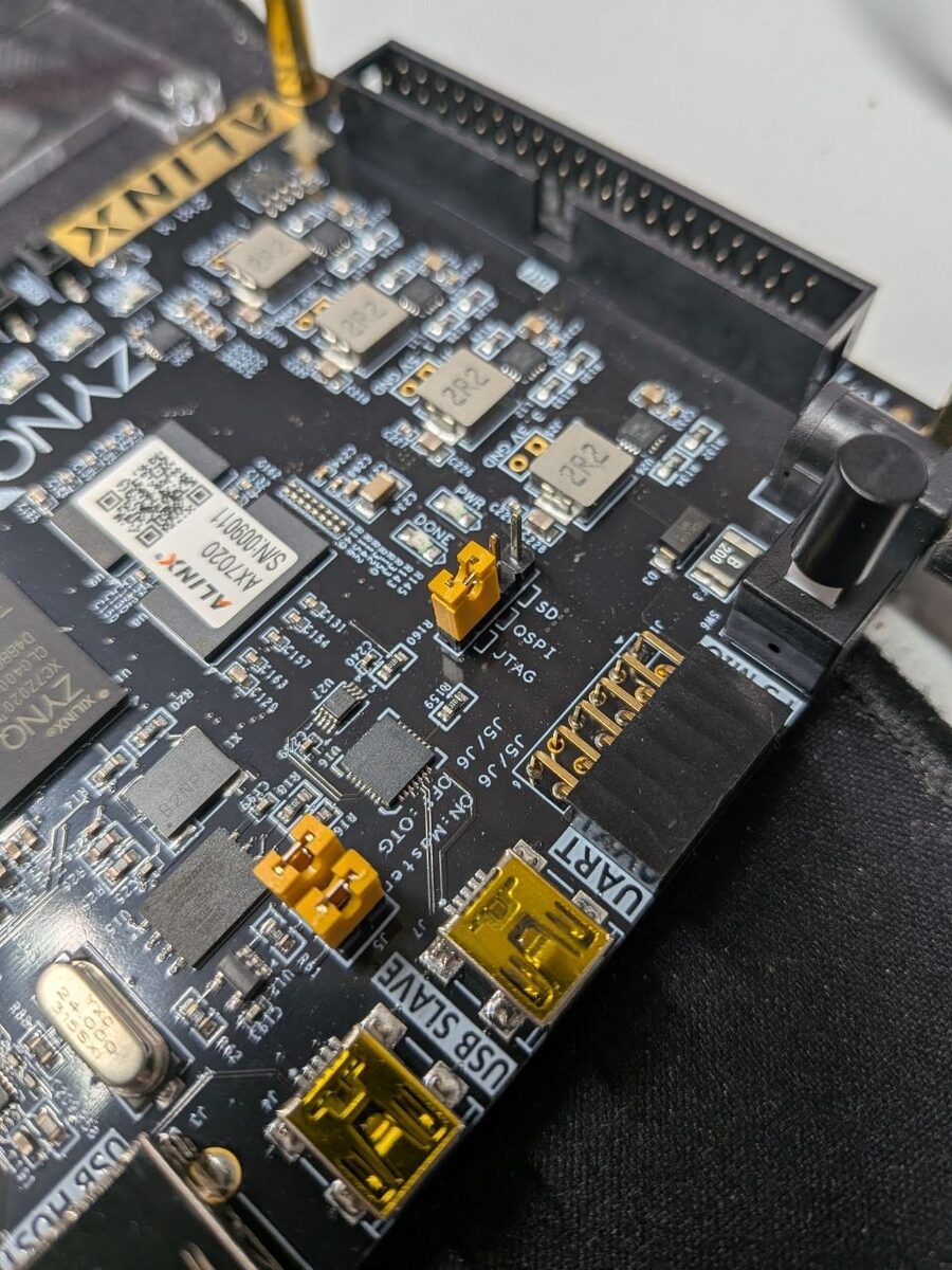
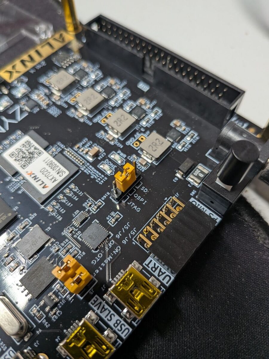
JTAG cable off, J13 from JTAG to QSPI, power on.
Checkpoint 7: the board boots entirely on its own. Before the power cycle, start two watchers on the host:
sudo journalctl -u NetworkManager -f | grep -i dhcp   # terminal 1: the lease
nc -u -l 6666                                         # terminal 2: the console
Then power on and check, in order:
- ~5 s after power-on a DHCP lease appears in terminal 1. That alone
already proves the whole chain: BootROM read
boot.binfrom QSPI, SPL ranps7_initand loadedu-boot.imgfrom flash, U-Boot proper brought up the GEM and randhcp. Find the address withip neigh show dev <usb-eth-if>(it changes every boot, random MAC). -
The netconsole broadcast arrives in terminal 2, ending in the line the
bootcmdprints:U-Boot 2026.10-rc2 (Aug 30 2026 - 20:25:52 +0200) modeboot = qspiboot AX7020 netconsole readymodeboot = qspibootis the important word: U-Boot read the boot-mode pins and confirms it was started from flash, not from a JTAG load. - The console is interactive:
tools/ncsh.py <ip> "bdinfo" "sf probe 0 30000000 0"must return the 1 GiB DRAM bank and the W25Q256, the same two answers as over JTAG, now without any cable except Ethernet and power.
If step 1 fails, SPL or the flash content is at fault and the board is mute; go back to the JTAG flow (Step 5) and check detours 8 and 9. If step 1 works but step 2 stays silent, U-Boot runs and only the console config is wrong (detours 4–6).
Stage 1 complete. The board boots an entirely open chain by itself, and the DHCP subnet on the USB adapter is already the foundation for Stage 2 (the image server).
The nine detours
Everything above reads like an afternoon. It was not, and here is why, chronologically, because several detours only make sense in sequence. If you bring up any Zynq board this way, expect to meet most of these.
1. SPL ran on the wrong core
After halt, OpenOCD’s current target is whichever core was last active,
often cpu1. resume <addr> sets the PC only on the current target. First
SPL run therefore happened on cpu1. Related trap: reg pc 0x0 + resume
does not restart a CPU cleanly; every other register keeps its crashed
state; use the address form, and always targets zynq.cpu0 first.
Fix, as it ended up: load-uboot.cfg begins with targets zynq.cpu0
immediately after init, repeats it after every halt, and starts loaded
code with resume 0x0 / resume 0x4000000 (the address form) instead of
setting the PC and resuming. The script encodes it so it cannot be
forgotten.
2. stdout=serial,nc silently ignored
Without CONFIG_CONSOLE_MUX and CONFIG_SYS_CONSOLE_IS_IN_ENV, U-Boot
ignores the console environment entirely and writes to UART only. The board
pinged; the console did not exist.
Fix, as it ended up: two lines in alinx_ax7020_defconfig,
CONFIG_CONSOLE_MUX=y and CONFIG_SYS_CONSOLE_IS_IN_ENV=y, plus the
CONFIG_PREBOOT that sets stdin/stdout/stderr = serial,nc after DHCP.
Only with all three does output actually leave over UDP.
3. Loading over a running U-Boot corrupts the image
Reloading u-boot.bin while the previous U-Boot was halted with MMU and
D-cache on: verify_image showed the DDR content wrong in 32-byte blocks:
one L1 cache line. Dirty lines from the old run were written back over the
fresh image. Flush with zynq.cpu0 cache l1 d flush_all around the load, or
better, load only while SPL (caches off) is halted. JTAG reads of DDR can
likewise return stale lines and fake a corruption.
Fix, as it ended up: the load sequence in load-uboot.cfg only ever
writes DDR while SPL is halted (SPL runs with caches off, so JTAG writes
land in DRAM directly), and every load_image is followed by
verify_image. For the rare case of reloading over a running U-Boot, the
repo README records the flush incantation
(zynq.cpu0 cache l1 d flush_all before and after the load).
4. lwIP has no netconsole
Since U-Boot 2026, lwIP is the default network stack, and
CONFIG_NETCONSOLE exists only in the legacy one. olddefconfig dropped it
silently; the binary had not a single nc_* symbol. CONFIG_NET_LEGACY=y.
Fix, as it ended up: CONFIG_NET_LEGACY=y in the defconfig, which
replaces CONFIG_NET_LWIP and lets CONFIG_NETCONSOLE=y survive
olddefconfig. Verification that the fix took:
arm-none-eabi-nm u-boot | grep nc_ must show the nc_* symbols, a
check worth adding to the build checkpoint whenever the config changes.
5. The distro bootcmd hides the prompt
In JTAG boot mode, distro_bootcmd loops forever through PXE/DHCP, and
while U-Boot is inside a network operation, netconsole drops all output.
Ping worked, console stayed dark. A harmless
CONFIG_BOOTCOMMAND="echo AX7020 netconsole ready" drops to the prompt.
Fix, as it ended up: that CONFIG_BOOTCOMMAND line in the defconfig.
It replaces distro_bootcmd, prints one recognisable line and falls
through to the prompt, which doubles as the success marker of
checkpoint 7. Once Stage 3 gives the board something real to boot, this
placeholder gets replaced by the actual boot command.
6. The host drops the packets, and the board wants slow input
Output arrived truncated: the board sent ~92 packets, the socket received
UdpRcvbufErrorsinnstat→ the USB NIC driver allocates ~16 KiB per frame, the 208 KiB default buffer fills after 13 tiny packets. Input had the mirror problem: characters sent back-to-back arrive scrambled (vobfsoforversion), because netconsole expects one character per packet, exactly what U-Boot’s owntools/netconsolescript does with a delay. Both fixes live intools/ncsh.py. Residual risk: a mangledsf writebecomesUnknown commandand writes nothing. It happened once; the read-back MD5 caught it. Check the echo of every destructive command.
Fix, as it ended up: both quirks are handled inside tools/ncsh.py:
a receiver thread with an enlarged buffer drains the socket continuously,
and input goes out one character per packet with 0.4 s spacing. The
residual character-loss risk is covered by procedure, not code: the flash
recipe in Step 6 always reads back and compares MD5 before anything counts
as written.
7. Never reset the PS from the debugger, and other one-way doors
Writing PSS_RST_CTRL (0xF8000200) over JTAG to get a “clean slate”
resets the debug logic too: cpu0 became unhaltable until a power cycle.
Same family of mistake: after any QSPI-mode boot, ps7_init has already
run, and it is not idempotent: JTAG-loading and restarting SPL on such
a board crashes at ever-changing places (undefined instructions in
uclass_find, alignment aborts in spi_nor_check_op) that cost an hour of
breakpoints before the pattern emerged. Rule: JTAG loading only on a board
freshly power-cycled with the jumper on JTAG. Flashing from a U-Boot that
SPL had handed the QSPI controller to was equally poisoned: Written: OK,
flash starting with zeros.
Fix, as it ended up: three procedural rules, written into
load-uboot.cfg’s header comment so they travel with the script: (1) never
write PSS_RST_CTRL from JTAG, because a power cycle is the only clean reset;
(2) JTAG-load only onto a board freshly power-cycled with J13 on JTAG, so
ps7_init has not run yet; (3) flash only from a U-Boot that was
JTAG-loaded in that state, never from one that SPL started out of QSPI.
8. bootph-all belongs on the flash node, not just the controller
First standalone QSPI boot: silence. The SPL DTB is produced by filtering on
bootph-*; the filter keeps matching nodes and their parents, not their
children. With the property only on the QSPI controller, flash@0 was
missing, and U-Boot 2026’s spi_find_chip_select() no longer has a
fallback that binds a jedec_spi_nor without a DT node. SPL died in
SPI probe failed., invisible without a console, and impossible to notice
in the JTAG flow, where SPL never touches the flash.
Fix, as it ended up: bootph-all; inside flash@0 in
zynq-ax7020.dts, in addition to the one on &qspi. Checkpoint 3 exists
precisely to catch this class of error on the host:
fdtget spl/u-boot-spl.dtb /amba/spi@e000d000/flash@0 compatible must
answer w25q256 jedec,spi-nor before the board is touched.
9. Quad read is broken in SPL, by three bytes
The deepest one. With spi-rx-bus-width = <4>, QSPI reads inside SPL come
back offset by 3 bytes. The image header is never recognised, SPL
silently falls back to its raw-image path and jumps into a uImage header.
U-Boot proper does not show the fault: sf read + md5sum from the
prompt happily verify a flash SPL cannot read, which sends the diagnosis in
every wrong direction first. Single-bit read (spi-rx-bus-width = <1>) is
correct. Two neighbours from the same digging session:
# CONFIG_SPL_STACK_R is not set (relocating the SPL stack to DDR produced
a corrupted stack pointer and alignment aborts, while plain JTAG memory
tests of the same region pass) and # CONFIG_SPL_LOAD_FIT is not set (the
SPL FIT loader placed the FDT at TEXT_BASE, so U-Boot executed a device
tree; the legacy uImage path is one header parse plus one copy, and 24 KB
smaller).
The trick that cracked detour 9 deserves its own mention: instead of moving
the jumper and power-cycling for every attempt, two temporary patches made
the QSPI load path debuggable over JTAG: map ZYNQ_BM_JTAG to
BOOT_DEVICE_SPI in arch/arm/mach-zynq/spl.c so SPL exercises the real
flash path in JTAG mode, and have _spl_load() write its breadcrumbs
(offset, size, read return, first words at the load address) into spare
DDR at 0x3f000000. One run, read the breadcrumbs: offset = 0,
size = 0x32000, the raw-image fallback, with the uImage magic sitting at
load_addr + 3. Revert both patches before building anything that gets
flashed.
Fix, as it ended up: three config decisions that are all visible in the
final DTS and defconfig: spi-rx-bus-width = <1> on flash@0 (single-bit
read; slower, correct; U-Boot proper is unaffected because only SPL
misreads), # CONFIG_SPL_STACK_R is not set (SPL stack stays in OCM), and
# CONFIG_SPL_LOAD_FIT is not set with u-boot.img built as a legacy
uImage. Whether quad read can be fixed properly (dummy-cycle configuration
for the W25Q256 in the Zynq QSPI driver) is an open question for later;
for Stage 1, correctness beats speed.
Closing
Nine detours for four files and ~40 lines of config. None of the individual facts was hard; what was hard was that almost every failure was invisible (no console yet), had multiple plausible causes, and sat in a different layer than its symptom: a host socket buffer masquerading as a board problem, a cache line masquerading as a flash problem, a device-tree filter masquerading as an SPI driver problem.
All self-written artefacts (the DTS, the defconfig, both OpenOCD configs
and both host tools) are published at
github.com/MaxClerkwell/ax7020-bringup,
including a README that covers the build and the ps7_init extraction from
the vendor package.
The next step is Stage 3 of the plan: a Linux built for this board with
Yocto instead of PetaLinux, replacing the next vendor black box in the
chain. The groundwork is already in place: U-Boot sits resident in QSPI, the
lab network with DHCP and TFTP is running, and bootm is waiting for a
kernel. (The image server of Stage 2 grows naturally out of the same lab
network along the way.) That build now has its own article:
a Yocto Linux in QSPI flash that fetches its own updates.